Choose the measurement system you want to configure.
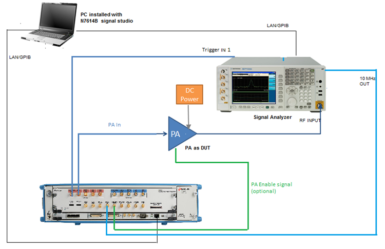
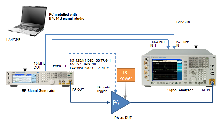
The following figure shows the instrument connection of EVM vs. Power measurement.
In the system connection diagram above, the dark blue lines are for RF connection; the light blue lines are for reference and trigger signal connection; the black lines are for instrument control connection with LAN or GPIB; the dotted line is for PA enable signal connection and it is optional for this test.
The BB TRIG 1 output (for N5172B/N5182B, TRIG OUT for N5182A, EVENT 2 for E4438C) may not act as the PA enable input for the PA directly because of the limit of its voltage and current output. The PA enable input can be provided by the user or generated with another functional generator using BB TRIG 1 output as a reference.
For the PA Enable Trigger connection, if you are using N5182A as RF Signal Generator, you need to route Marker 2 output to TRIG OUT port manually by pressing Dual ARB, Marker Utilities, Route Connectors, Route to Trig Out BNC, BBG Markers, Marker 2 on the front panel.
The table shows the requirement for the instruments used in DPD measurement. For details about the options required for each instrument model, refer to System Requirements.
| Instrument Type | Instrument Model Supported |
|---|---|
| RF Signal Generator |
E4438C ESG E8267D PSG N5182A MXG N5182B MXG N5172B EXG |
| Signal Analyzer |
N9010A EXA N9020A MXA N9030A PXA |
To set up the measurement system, follow the steps below:
Connect the PC installed with N7614C Signal Studio with the RF Signal Generator and Signal Analyzer through LAN or GPIB.
Connect the EVENT 1 port on the rear panel of the RF Signal Generator to the Trigger IN 1 port on the rear panel of the Signal Analyzer using a BNC cable. This is to synchronize the RF Signal Generator and Signal Analyzer in time domain.
Connect the 10 MHz OUT port on the rear panel of the RF Signal Generator to the EXT REF IN port on the rear panel of the Signal Analyzer using a BNC cable.
(Optional) Connect the BB TRIG 1 port (for N5172B/N5182B, TRIG OUT port for N5182A, EVENT 2 port for E4438C) on the rear panel of the RF Signal Generator to the PA enable port of the PA.
If you are using N5182A as RF Signal Generator, you need to route Marker 2 output to TRIG OUT port manually by pressing Dual ARB, Marker Utilities, Route Connectors, Route to Trig Out BNC, BBG Markers, Marker 2 on the front panel.
Connect the RF OUTPUT port of the RF Signal Generator to the input of the PA and connect the output of the PA to the RF INPUT port of the Signal Analyzer.
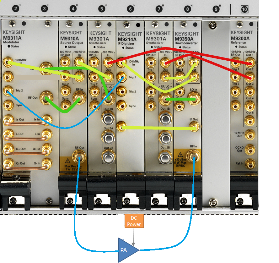
If PXI VSA and VSA are located in different PXI chassis, then more external HW are needed to implement the synchronization to same reference clock. To simply the scenario, Bumblebee supposed to support PXI VSG and PXI VSA from same chassis only. Below is the typical HW connection for Bumblebee DPD.
Start by following the typical connection guide from the user manual to ensure the independent PXI instrument is working well.
Cable between Trig 2 connector  of M9311A and Trig 1 connector
  of M9214A are mandatory for Bumblebee DPD.
100 MHz reference clock signal of VSG and VSA should be from same reference module M9300A.
Connect DUT between RF out of PXI VSG and RF in of PXI VSA.
Below is the typical hardware connection which are using the output of DIRECT OUT  connector of channel 1 to provide input signal of power amplifier. Because channel 1 is used here, then the SAMPLE MARK OUT
  of channel 1 is connect to the trigger 1 connector of signal analyzer. If PA is needed to test in burst mode, then
SYNC MARK OUT 1
of channel 1 is connect to the trigger 1 connector of signal analyzer. If PA is needed to test in burst mode, then
SYNC MARK OUT 1  is connect to the PA Enable of power amplifier. Otherwise this connection can be ignored. To keep the M8190A and signal analyzer to use same reference signal, the 10MHz reference out must be connected the REF CLK IN
  . Regarding the input signal of DUT, there is also other output of channel 1 can be used
  .
.
Same connection definition can be applied to channel 2 if channel 2 is selected.